
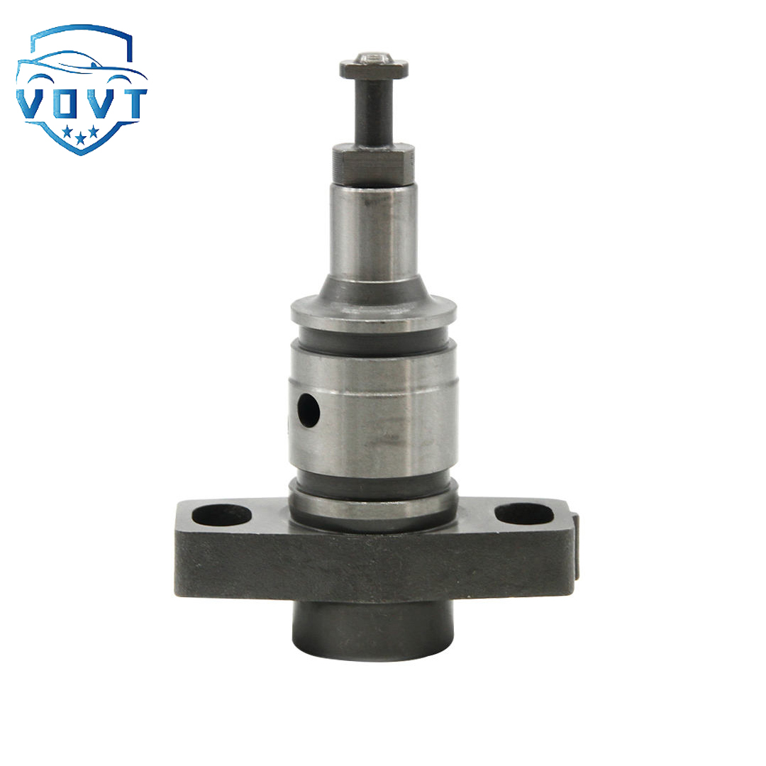
Genuine Quality New Diesel Plunger for C7 C9 Plunger Barrel Assembly for Fuel Pump Engine Spare Parts


products description
| Reference. Codes | C7 |
| OE/OEM Codes | / |
| Application | / |
| MOQ | 5 PCS |
| Certification | ISO9001 |
| Place of Origin | China |
| Packaging | Neutral packing |
| Quality Control | 100% tested before shipment |
| Lead time | 7~15 working days |
| Payment | T/T, Paypal, Western Union or as your requirement |
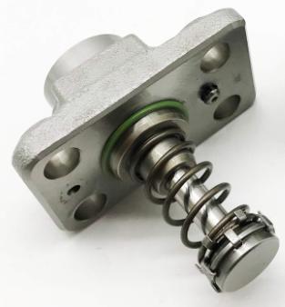
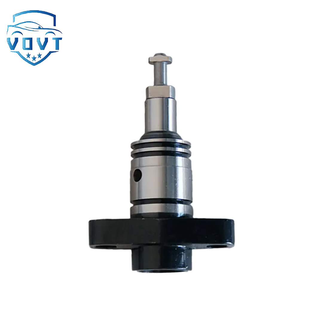
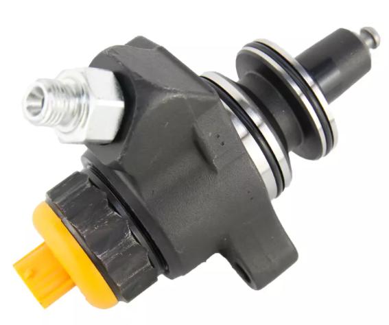
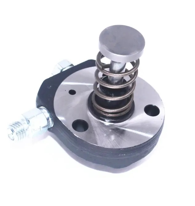
Injector plunger assembly
The injector plunger assembly is a key component in the injector, mainly used to accurately control the injection amount and injection time of the fuel. The following is a related introduction:
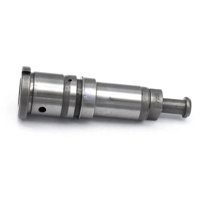
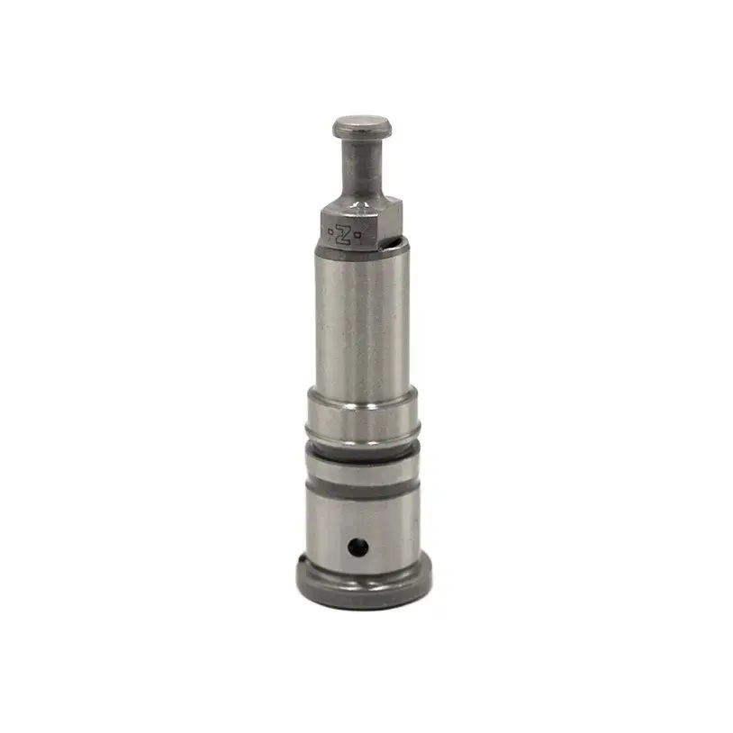
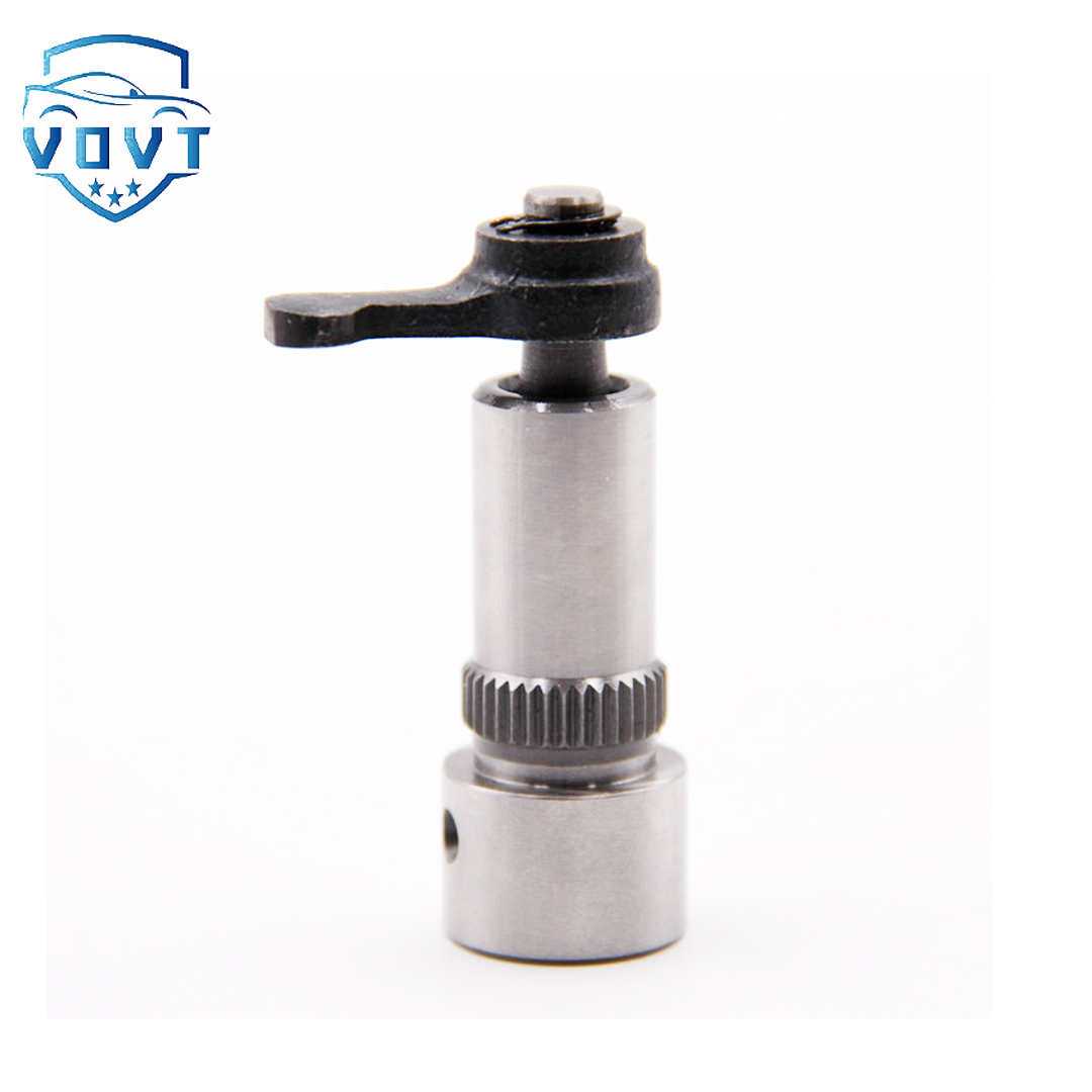
Structural composition
Plunger: Usually a precision-machined cylindrical metal part, the surface is high-precision ground and polished to ensure good sealing and sliding performance between the plunger sleeve. The plunger is provided with a spiral groove or a straight groove to control the flow and injection amount of the fuel.
Plunger sleeve: It is a sleeve that cooperates with the plunger and also has high-precision processing requirements. There are oil inlet holes and oil outlet holes on the plunger sleeve. The oil inlet hole is connected to the fuel supply system, and the oil outlet hole leads to the injection nozzle. A sealed fuel cavity is formed between the plunger sleeve and the plunger.
Spring: Generally, a high-strength coil spring is used and sleeved on the plunger. The function of the spring is to quickly return the plunger to its position after the injection is completed, ready for the next injection cycle.
Other components: It may also include plunger caps, guide sleeves and other components. The plunger cap is used to fix the spring and plunger, and the guide sleeve helps to ensure the movement accuracy and stability of the plunger.
Working principle
Oil suction process: When the electromagnetic coil of the injector is not energized, the plunger is in the lowest position under the action of the spring force. At this time, the oil inlet hole on the plunger sleeve is opened, and the fuel enters the fuel chamber between the plunger sleeve and the plunger under the action of the fuel system pressure to complete the oil suction process.
Injection process: When the electromagnetic coil is energized, a magnetic field is generated to attract the plunger to move upward to overcome the spring force. When the plunger moves upward, it first closes the oil inlet hole, and then continues to squeeze the fuel in the fuel chamber upward, causing the fuel pressure to rise sharply. When the fuel pressure reaches the opening pressure of the injector, the injector opens, and the fuel is sprayed into the engine combustion chamber in a high-pressure injection manner.
Return process: After the electromagnetic coil is powered off, the magnetic field disappears, and the plunger quickly returns downward under the action of the spring force. The volume of the fuel chamber increases, the pressure decreases, the injector closes, and the injection stops. At the same time, the oil inlet hole opens again to start a new round of oil suction process.
Function
Precisely control the amount of fuel injection: the volume of the fuel chamber is changed by the up and down movement of the plunger, so as to accurately control the amount of fuel injected each time. According to the different working conditions of the engine, such as load, speed, etc., the electronic control unit will control the operation of the injector plunger assembly to provide a suitable amount of fuel injection to ensure the power output and fuel economy of the engine.
Control the injection time: the movement timing and speed of the plunger determine the start time and duration of the fuel injection. Precise control of the injection time is crucial to the combustion process of the engine, which enables the fuel to be injected into the combustion chamber at the best time, fully mixed with the air and burned, improve the combustion efficiency and reduce pollutant emissions.
Products categories
-

Diesel Fuel Pump Plunger 0941500618 For Excavator
-
Fuel Pump Plunger F01M100869 For Bosch CP1 Fuel...
-

Best Selling New Diesel Pump Plunger P388 Plung...
-

Brand New Diesel Fuel Injection Pump Plunger &#...
-

China Made New Diesel Pump Plunger A161 Plunger...
-

China Top New Diesel Pump Plunger 090150-7653 P...
-

China Top New Diesel Pump Plunger 2 418 455 542...
-
China Top New Diesel Pump Plunger PH9 Plunger B...
-
Common Rail Fuel Injection Pump Plunger 094150-...
-

Common Rail Injection Pump Plunger 094150-0330 ...
-
Common Rail Pump Plunger 294090-0080 294090-009...
-
Diesel Fuel Injection Pump Element Plunger 0901...
-
Diesel Fuel Pump Plunger 2418441001 for BENZ OM422
-
Diesel Injection Pump Plunger 2455-429
-

Diesel Pump Plunger PB202 For ASIMCO
-
Factory Direct Sales New Diesel Pump Plunger 51...


