
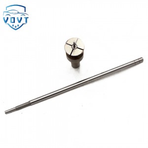
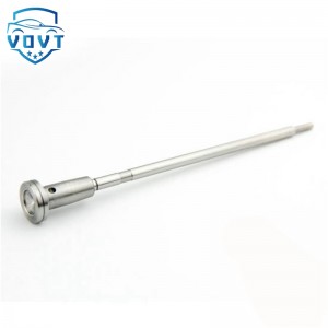
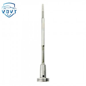
High Precision Injector Control Valve F00VC01349 Common Rail Control Valve Set Assembly For Injector 0445110249 0445110250


Products Description
| Reference Codes | F00VC01349 |
| Application | / |
| MOQ | 6 PCS |
| Certification | ISO9001 |
| Place of Origin | China |
| Packaging | Neutral packing |
| Quality Control | 100% tested before shipment |
| Lead time | 7~15 working days |
| Payment | T/T, L/C, Paypal, Western Union, MoneyGram or as your requirement |
Valve assembly installation operation
The installation operation of the valve assembly is a complex and meticulous process, involving the correct assembly and adjustment of multiple components.
1. Preparation before installation
Check the water supply network: Make sure that the water supply network has passed the pressure test and flushing, and all connectors are tightened.
Check the pressure reducing valve: Confirm that the specifications and models of the pressure reducing valve are consistent with the design, the valve body appearance is intact, and remove foreign matter in the valve.
Prepare tools: Prepare the tools required for installation, such as special tools, push rods, hammers, etc.
2. Install the pressure reducing valve
Install the pressure reducing valve: Install the pressure reducing valve in the selected position and ensure that it is firmly installed.
Connect the inlet and outlet: Connect the water inlet and outlet of the pressure reducing valve to ensure that the connection is tight and there is no leakage.
Install the pressure gauge: If the pressure reducing valve itself does not have a pressure gauge, a pressure gauge should be installed in the adjacent parts before and after.
Install the filter: Install the filter on the water inlet side and install the control valve before and after it.
3. Installation of diesel engine valve assembly
Cleaning parts: First clean the parts of the valve assembly.
Apply engine oil: Apply clean engine oil to the valve stem and the working bevel of the head.
Install valves and valve springs: Insert the valve into the guide tube into the valve seat to ensure correct installation.
Inspect installation: After installation, check that the locking clip of the valve assembly fits tightly with the tapered groove of the valve stem and the tapered hole of the spring seat. The height difference between the two locking plates should not exceed 0.3mm, and the height of the locking plate protruding from the spring seat should be between 0.25 and 2mm.
Products categories
-

Auto parts Diesel Fuel Injector Control Valve F...
-
High Quality New Common Rail Injector Control V...
-

Auto parts Diesel Fuel Injector Control Valve F...
-
New Common Rail Valve F00RJ01941 for Bosch Inje...
-
High Precision New Diesel Fuel Injector Control...
-

High Quality New Common Rail Injector Control V...


